9: PID and Motor Control
About this Project
This project will be a culmination of all the skills you have learned in OPS. There are two possible tracks you can go down:
- Wall-E: Build a miniature car that follows walls/avoids objects around it
- RC Car: Control a car by using the HC-05 and Processing IDE to control it
To do this, you will design your own PCB, and implement a PID controller in software. This project will be more challenging than the previous ones, but the design constraints are more open ended, allowing you to make some design decisions yourself.
Lecture Slides
Prerequisites
Skills Learned
- PID Controller
- UI/UX Design
- Iterative Design
Parts List
Since this project is open ended, different groups will likely use a variety of parts. Many parts, such as breadboards, IR emitters/receivers, or IMUs, can be reused from previous labs. The new parts you will likely need are:
| Part | Quantity | Estimated Cost | Example Vendor |
|---|---|---|---|
| Ball Caster | 1 | $2.99 | Pololu |
| Wheels | 2 | $7.98 | Pololu |
| Gear Motors | 2 | $12.08 | Amazon |
Total estimated cost assuming part reuse: $23.05 per team of 2
Section 1: Being a Mechanical Engineer
Powering Your Car
Because our final goal is to have a car following some object, we want it to be powered wirelessly through 9V batteries instead of through our computer’s USB port. While we test our vehicle however, the motors require a large amount of power, which would mean we’d need to go through a lot of 9V batteries (not very cost effective). For that reason, when testing and implementing the motors, power the car through your computer. The motors will not go very fast; however, that’s fine for now. When you’re trying to implement later functionalities of the car, you can use the 9V batteries. In the end, your car must be battery powered.
Motors
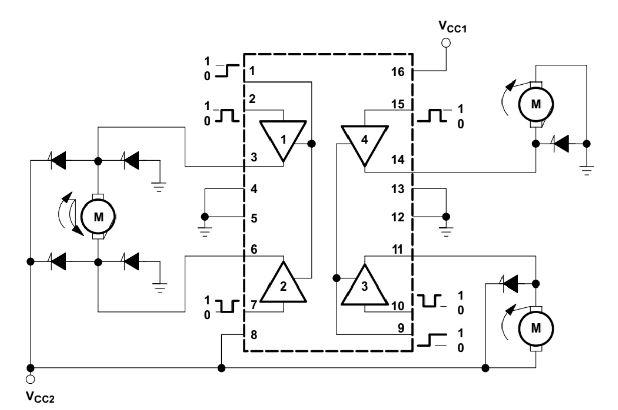
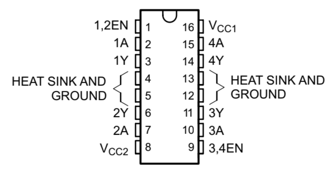
We will be using the L293D IC to control our motors. The nice thing about the L293D chip is that it has 2 H-bridges, a fantastic circuit to drive motors!
yikes this looks bad!
Thankfully, we’re going to treat this IC like a black box, with each side of the L293D controlling one motor. All we need to know are the inputs and outputs of this device to get it to work properly! (whew!)
- Power Supply
- pins: 4, 5, 8, 12, 13, 16
- VCC1 (pin 16) drives logic levels. You need to connect this pin to 5V on the Nano
- VCC2 (pin 8) drives the motors. You need to connect this pin to Vin on the Nano
- 4, 5, 12, 13 are ground pins
-
Direction Inputs
- pins: 2, 7, 10, 15
- IN1, IN2 controls one motor( ie: left motor) IN3, IN4 controls the other (ie. right motor)
- connect to any digital pins on the Nano
-
Directional Logic:
EN IN1 (IN3) IN2 (IN4) Direction HIGH LOW LOW STOP HIGH HIGH HIGH STOP HIGH HIGH LOW FORWARD* HIGH LOW HIGH BACKWARD* LOW x x COAST** - * these depend on how you set up your circuit and you will need to adjust this
- ** setting the EN pin to LOW will let the motor coast to stop, regardless of input at IN1, IN2
- Speed Input
- pins: 1, 9
- connect to PWM pins on the Nano in order to create variable outputs to motor
- note: EN1 denotes the left hand side while EN2 denotes the right hand side of the IC
- Output
- pins: 3, 6, 11, 14
- connect these to the leads of your motor to output what your L293D has done
Tips
- L293D has a notch/dot to mark the top of it. Use that to orient your board
- Your l293D should go over the middle gap of the breadboard. You don’t want to short circuit your board!
Test the Motors
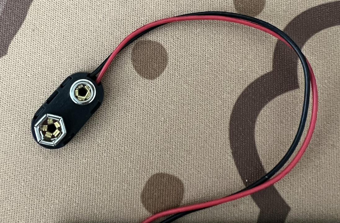
Don’t forget to pick up a 9V battery connector. It should look like this:
Please note that the motors do not have wires soldered to them already. Which means you’ll have to solder on the wires to the two spots near the front of the motor like so:
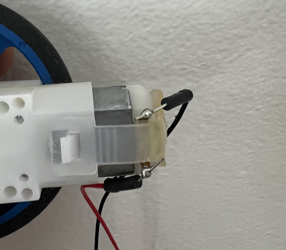
*don’t solder jumper wires to this instead, use the solid core BLACK wires on the spool.
Forward/Backward
Once you’ve wired up your motors to the IC, it’s time to do some testing. We’ll first start off with the simple output: moving forward and backwards. We recommend testing one of the motors to make sure it’s wired up correctly and it moves forward/backward with the appropriate logic. Then, mirror the wiring on the other side!
Turns
Turning your wheels is quite simple! In the forward and backward direction, we had the motors moving in the same direction. When we want the car to turn however, what we’ll do is have one motor move forward while the other moves backwards!
Speed
Here is some code to test your motors on different speeds. Notice that we are using PWM signals to generate varying motors speeds! Every motor is slightly different, so make sure to note at what PWM signal your motor starts to turn. This marks the threshold with which your car will/won’t move.
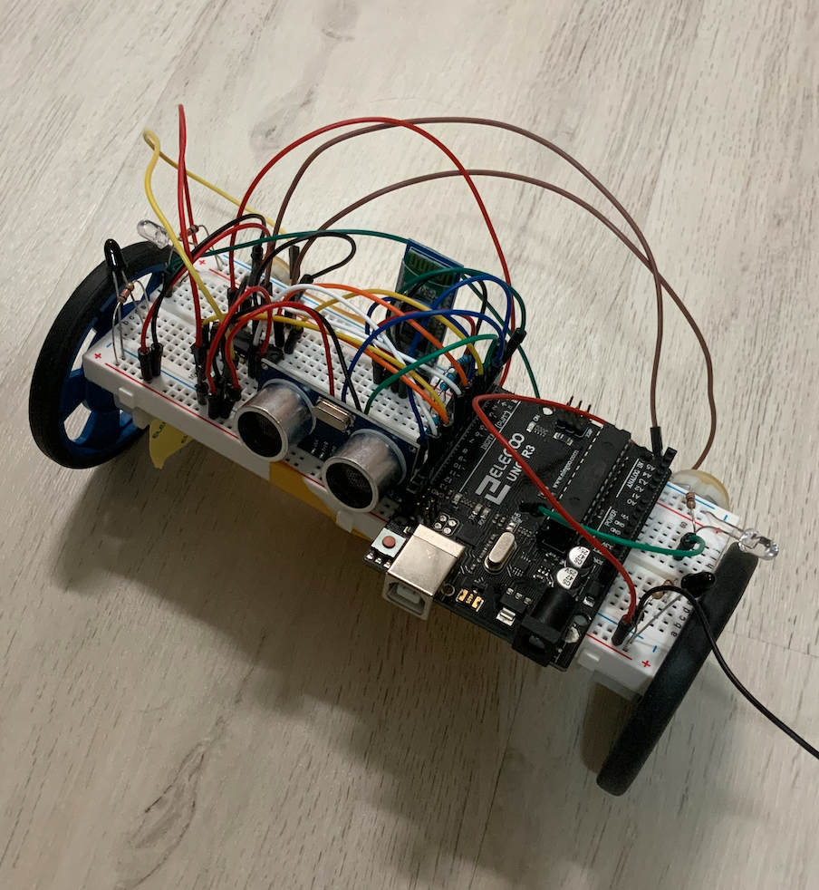
What Makes a Car?
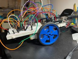
It’s important to plan out your wiring before building your car to ensure that everything fits on it. We recommend color coding as much as you can as well as this will help a lot with debugging! Try to build your car one function at a time. (ie: make sure motors work, then your sensors, etc)
Make sure you put the ball swivel on the bottom of the car along with the motors in order to balance the weight of the car.

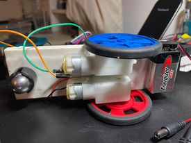
Here are some examples of how you can attach your motors.
Your options:
There are two options for your car’s functionality: create a wall following car/a car that follows an object or an RC Car controlled by your computer.
We will be using feedback loops (hint hint, PID controls) in order to control our car and make sure it does exactly what we want it to!
| Car Configuration |
|---|
 |
|
Sensors
Regardless of which type of car you choose to implement, you will be using the IR Sensors.
Section 2: PID Control
No matter which mode you choose to implement, the idea of feedback control is the same. You want to use the sensor readings to adjust your output to the motors. This part of the spec will go over the high-level idea and code structure for the two recommended ‘autopilot’ modes (A, B) listed above. Part 3: P(I)D will list a set of steps you might find helpful in tweaking your constants.
Hand-Following
The goal of your PID controller is to maintain some target distance between your car and the hand/object you’re leading it with. Note that using a flat, light-colored object will work better than your hand to get more consistent sensor readings.
For this option, you may assume the two motors are similar enough; the car will go in a relatively straight line if the two motors are set to the same speed. This option only uses one sensor (the ultrasonic sensor). Following the object moving in a not-straight direction is not required, though you can implement it by installing more ‘IR pairs’ (see A Note on IR Pairs).
Here the general idea of how the proportional and derivative term should be used:
- Define ‘error’ to be the distance between your car and the object minus the target distance
- The proportional term should be used so that the car
- speeds up when object is far away
- slows down when object is closer
- goes backwards when target is too close
- The derivative term should be used so that the car changes velocity
- faster if error has been increasing
- slower if error has been decreasing
Wall/Object-Following
In this project we need to use PID to ensure we do not stray away or into a wall, and instead just travel parallel to it. You may currently be thinking, “Hey, I can just start it parallel to the wall and have it go forward like I already programmed, this project is so easy!” Unfortunately, most cars will not travel in a perfectly straight line due to differences in imperfect motors and uneven weight distributions on the car, plus we are gonna ask to see your final code :).
Now on to how we implement it, we start by deciding the target distance we want the car to be from the wall. This value is up to you, can be determined experimentally, and may not be actually expressed as a distance but instead a target IR reading. Now while the car is moving along the wall you can take (near) continuous readings from the IR and determine the error from the target value. With this error value, and the pid error constants you should adjust the speed of each wheel to correct the path (increasing the speed of the right wheel and decreasing the speed of the left wheel turns the car left; vice-versa for a right turn). Remember the car is moving forward the entire time, but changing its direction according to the error.
- The proportional term should be used so that the car
- Heads towards the wall when it is too far away
- Heads away from the wall when it is too close
- The speed at which it heads towards or away from the wall depends on how close or far it is
- The derivative term should be used so that the car changes its velocity
- Faster if the error is increasing
- Slower if the error is decreasing
Once you correctly implement the wall tracking the last (and probably easier) part you have to code is the corner detection. Essentially you will utilize an IR pair to detect an upcoming corner and execute a set of instructions that make your car turn 90 degrees along the corner. These instructions will be independent of and essentially override the PID decisions until it completes the turn. Once it completes the turn it will return to tracking along the new wall. It is up to you the best set of instructions to give your car to make the turn. See A Note on IR Pairs for more details on this part of the project.
Section 3: P(I)D
Tuning the constants for the proportional, (integral), and the derivative term is done by trial-and-error, for the most part. However, there are some things you may want to keep in mind, and some ways to do this more efficiently than randomly hard-coding different numbers and uploading the Arduino code 1000 times.
Before you get started, note the following values:
- Minimum PWM duty cycle to make your motor run (min_speed)
- Ranges of raw IR readings
The idea is to multiply the raw ‘error’ value by an appropriate constant to be able to map it to analogWrite parameters that minimize the error.
- Start by setting all constants to 0
- Increase Kp incrementally, until it is responsive but not too jittery
- It might be easier to do this step without actually making the motors turn, until the numbers outputted by your controller seems reasonable (between min_speed and 255 and changes as expected)
- Use the Serial Monitor!
- Once you’re satisfied the numbers you see, check the proportional control with your motors turning, target moving
- Repeat #2 for Kd (, Ki)
- Remember: start small, observe values before analogWrite’ing them
*The integral constant you settle on may be very small or even 0; this is okay as the integral control is related to accumulated error over time, which is more relevant if the point you are trying to reach changes rapidly. In both projects proportional and derivative control should be sufficient for reaching the target distance, but we still recommend testing this for yourself.
Hints
- pulseIn(pin, HIGH/LOW)
- We want to measure the elapsed time between a rising edge (LOW to HIGH) and a falling edge (HIGH to LOW) on the echo pin. So the second parameter should be set to HIGH, and the first to the Arduino pin that is connected to the ECHO pin on the HC-SR04.
- It is possible that the speed adjustments caused by PID control will want to write out a speed outside of the acceptable range (minspeed-255). You may want to include a line that constrains the possible output to that range.
- When deciding how much to change your speed by each control constant should multiply the corresponding error (kp _ error, kd _ derivative of error, ki* integral of error) and then add up the terms which will result in a final sum that influences the change in speed for your wheels.
- Finding the derivative and integral of error may not be obvious at first, one function that might help is millis() which returns the amount of time that has passed since the Arduino was reset in milliseconds. If we record the time in each loop and take the difference in successive loops we can find the amount of time elapsed in the previous loop.
- With the calculated time we can find the approximate derivative and integral, which will be a good approximation since our time intervals are small (think back to Calc class, average slope and Reimann sum)
- Code Outline
A Note on IR Pairs
We will be using the same IR sensor pairs from our distance sensor project for this project. Please note, if you are running into issues with the emitter for any reason, you can actually use a Red LED in replacement because our receivers respond to light in the infrared range.
Again, if you run into issues with your emitter, just replace it with a Red LED and use the same build as you did in the previous project.
Additionally, you should recall the purpose of what you are using the IR pair for in this project when implementing it; you are not changing the brightness of an LED, you are sensing a distance. It will be difficult to implement PID with the pair since the LED and receiver have a limited spectral overlap, so in most cases detecting a threshold analogRead() value from the receiver will be the extent of its use.
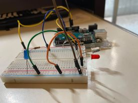
In the above circuit the red LED and IR receiver form an IR pair. As the board moves along a wall the IR reading hovers around some value; as the board approaches a corner the pair will approach a wall. As they approach a wall, red light will be reflected back to the receiver and the analog reading will decrease. Once the reading is below a certain threshold (which you can discover experimentally) the board is now too close to the corner and will turn on the blue LED to indicate that it will hit the wall or maybe execute a set of commands that cause it to rotate 90 degrees (hint hint).
FAQ
What orientation do the LED and Phototransistor go in?
- For the LED, on the board, the footprint has a flat side to the circle outline. On the LED, there is also a flat side that matches with the footprint. For the phototransistor, you will have to refer to the datasheet and the schematic for your board. On the datasheet, there is a diagram which shows you what the longer and shorter pins are.
What value resistors should I use for R1 and R2 on the IR sensor board?
- The resistor connected to the IR LED should be 130 Ohms, and the one connected to the IR Phototransistor should be 10 kOhms. Refer to your Eagle schematic and board design to determine which resistor is which. Remember that SMD Resistors have an orientation while SMD capacitors do not.
How do I attach the motors and ball caster to the breadboard?
- The back of the breadboard has an adhesive that the motors and ball caster can be stuck to. You have to remove the paper that is covering the adhesive.