7: Serial Communication

About this Project
In this project, you will be implementing a 2-Arduino game called Red Light, Green Light. In this game you are a carduino playing against a randomly generated stoplight: You must move at a green light, and stop at a red light; should you run over a red signal, or stay put at a green signal, you lose. If you get it right, you’ll gain a point and move to the next intersection.
Lecture Slides
Prerequisites
Skills Learned
- Pull-up/pull-down resistor
- Serial protocol: UART (Universal Asynchronous Receiver Transmitter)
Parts List
| Part | Quantity | Unit Cost | Example Vendor |
|---|---|---|---|
| Arduino Nano | 1 | $4.00 | Amazon |
| Mini USB Cable | 1 | $1.80 | Mouser |
| Breadboard | 1 | $1.50 | Amazon |
| Green LED | 1 | $0.12 | Digikey |
| Red LED | 1 | $0.14 | DigiKey |
| White LED | 1 | $0.17 | DigiKey |
| HC-05 Bluetooth Module | 1 | $10.39 | Amazon |
| Push Button | 1 | $0.23 | DigiKey |
| 10k Ohm Resistor | 1 | $0.10 | DigiKey |
| 100 nF (0.1 uf) Capacitor | 1 | $0.49 | Digikey |
| 200 Ohm Resistor | 6 | $0.10 | DigiKey |
| Speaker | 1 | $0.90 | Digikey |
| Potentiometer | 1 | $0.95 | Adafruit |
Total estimated cost: $TODO per team of 2
If reusing Arduino/MiniUSB/Breadboard: $TODO per team of 2
Project Specification
One microcontroller (representing the stoplight) will flash one of the two red/green LEDs and the other microcontroller (representing the Car and its gas/brake pedals) will have two tactile switches (fancy word for buttons). Press the gas at green lights and the brake at red lights in order to score points and move to the next intersection. Get it wrong and you lose!
The goal of this project is to teach you how to use Serial communication and give you your first experience with communication protocols before we move on to more sophisticated and complex protocols.
Reference Material
This lab requires reading documentation and datasheets. Here are some resources that you will reference throughout the project.
- Lecture 7 Slides
- Arduino Nano DataSheet
- Arduino Nano Pinout
- Arduino Serial Library
- Arduino
random()Function - Processing Language Reference
- HC05 Connection Tutorial
Checkpoint 1: Getting UART Working
This is a group project! Team up with a partner!
-
Wire up your MCU to your HC-05 so we can get them talking using the Serial library. To read and write between hardware devices, use the Serial library’s read and write functions. Also, make sure that you are first checking that there is available serial data before reading from Serial. To print text to your Processing screen on your computer use the print or println functions as we have done before. Remember that data transmitted by one MCU is data received by the HC-05. Connect the Tx of one device to the Rx of the other device and vice versa. Make sure you also connect GND pins on both devices to each other so they share a common ground.
NOTE: DO NOT CONNECT THE TX RX PINS WHEN UPLOADING A SKETCH TO YOUR ARDUINO. Disconnect these pins when uploading code and reconnect them after the code is done uploading.
-
Write two sketches, one for the Arduino, and one for Processing:
-
The Arduino sketch should accomplish the following:
-
Check for the hardware button press, if it was pressed then set the point value to zero.
- This is done so we don’t have to reset the Arduino module if we want to replay (and thus don’t have to reconnect over bluetooth)
-
Randomly generate a color for the stoplight intersection 2. Can be done using characters such as ‘r’ or ‘g’ to signify ‘red’ and ‘green’ respectively
- Can also be done using integers such as ‘1’ or ‘0’.
-
Light the appropriate LED using the randomly generated item from before
- I.E. if the char was ‘r’ light the red LED
-
Read from the Serial buffer if there is data available
-
Make sure to implement a wait to read which can be done with:
-
While
Serial.available == 0 {}- Do nothing loop (just waits until there is data)
-
Some type of software identifier
-
-
Use
Serial.read()to log the data from bluetooth
-
-
Identify whether or not the move sent over bluetooth was the correct move. This portion must meet the following requirements:
-
IF CORRECT:
-
One point must be added to the scoreboard
-
A “happy tone” must be played from the buzzer for half a second
-
Choose some arbitrary high pitch
-
You’ll likely want to include pitches.h
-
-
Have the white LED flash once per the number of points
- If 10 points there should be 10 flashes
-
-
IF INCORRECT:
-
Points must go back to 0
-
The Red LED must turn on for 5 seconds
- While it is on a “mad tone” must be played from the buzzer for an equal amount of time
-
-
-
The number of points should be printed back across serial communications to the host device
- Use
Serial.println()
- Use
-
-
The Processing Sketch should accomplish the following:
-
Have two digital buttons
-
One for GO
- Must be green
-
One for STOP
- Must be red
-
Buttons must be functional and send data across bluetooth to HC05 for MCU processing
-
-
Display the point count at the bottom of the screen
-
The majority of this code will be given to you, with comments describing the general UI functionality. It is not a requirement of this game for you to make a beautiful UI, but it is a requirement for it to be functional. Feel free to alter the looks however you like once the functionality is working
-
-
Checkpoint 2: Wiring Up Hardware
Creating the green and red lights: You will need to hook up 2 different output LEDs to your Stoplight Arduino. Remember, LEDs can burn out if more than 20mA of current passes through them, and usually you want to limit current to <=5mA to save energy and to prevent the LED from being too bright. Make sure to include a current-limiting resistor in series with your LEDs. The digital pins output ~5V when you write HIGH.
Points reset: Your RC-carduino will have 1 push button input that represents the points reset. If the button is pressed the number of points should return to their default state of zero.
NOTE: Button Debouncing.
When you press or release a button, it will “bounce” several times before reaching its final state, which means several button presses will be registered.
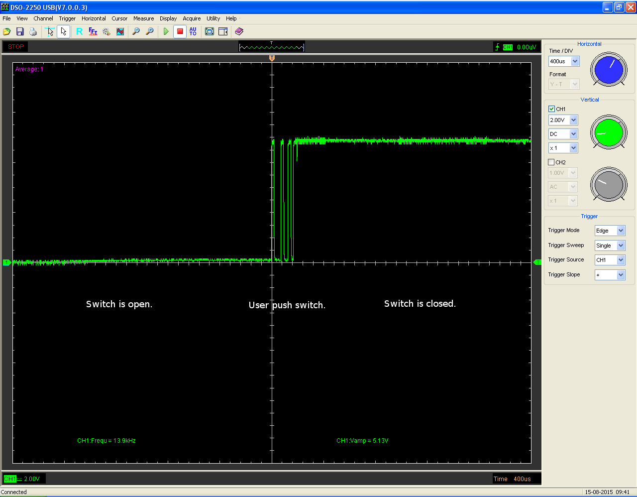
One way to avoid this is to put a capacitor in series with the button, so that the button release will not register until after the capacitor is fully discharged over time. If the capacitor’s value has been appropriately chosen, this will be after the button has finished bouncing, such that only one press will be registered. Below is the basic circuit for button debouncing:
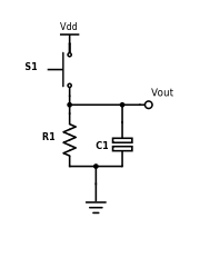
Vout is the voltage read by the microcontroller input pin, and Vdd is +5V. Use a 10k resistor and a 100nF capacitor for your debouncing circuit, so that you achieve an RC time constant of 1ms (time constant = resistance * capacitance).
NOTE: This debouncing circuit also includes a pull-down resistor, so that Vout is HIGH when the button is pressed, and LOW otherwise. Also, the RC constant can be a complicated topic, but for now it is sufficient to understand that it is the product of resistance and capacitance, and corresponds to the amount of time the circuit debounces.
-
Draw the full schematic (on paper). After you get checked off, continue onto..
-
Write a sketch and build the circuit to light up each LED on one Arduino while its corresponding button on the other is pressed down. When a button is released, the LED should turn off.
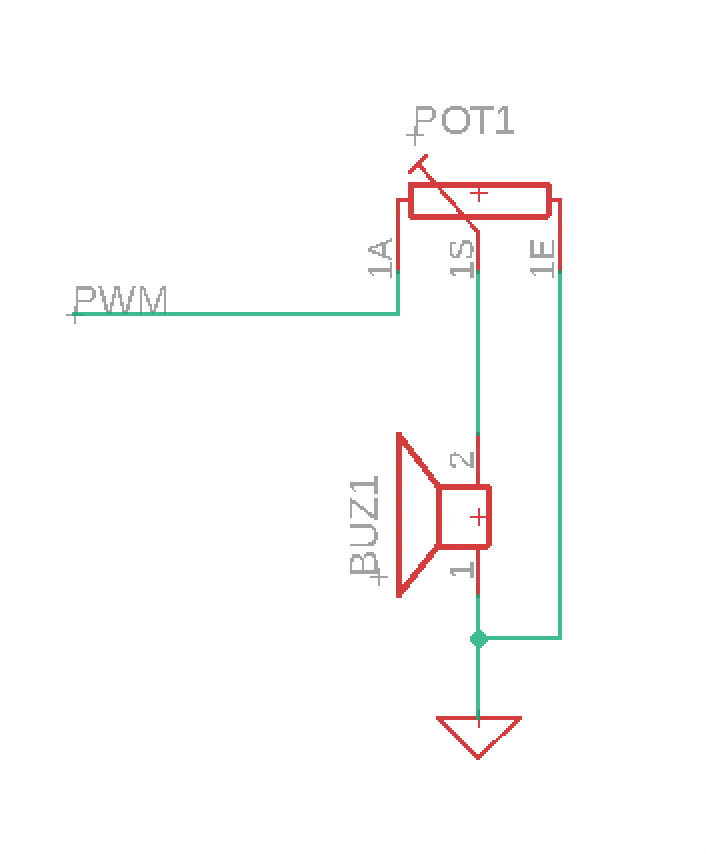
Buzzer Scoreboard: Wire a buzzer to a PWM pin on your MCU. When we add a current limiting resistor in series to this buzzer the sound outputted by the speaker should decrease, as the power delivered to the buzzer decreases. We know buzzers can get annoying at times, so because of this you must implement a series potentiometer into your circuit to variably alter the output volume of your speaker.
Game Requirements
- Two different colored LEDs (used for stoplight)
- One white LED (used for points identification on RC-carduino side)
- The Stoplights flashes one of the LEDs; the color chosen should be as random as possible (check the reference materials above for more information);
- On Processing IDE (Player Module), the player should press the button that matches the LED the Controller flashed (i.e. Gas for Green Light, Brake for Red Light)
- The Stoplight should wait until a button is pressed in Processing (Player Module). The player must press the correct button.
- If the player presses the correct button, the white LED must blink the number of points allotted and a point must be added to the player’s score. The buzzer scoreboard should play a high pitched tune briefly. A new round must begin.
- Should the player lose (by pressing the incorrect button), the red LED should turn on for 5 seconds, the buzzer scoreboard must play a low tone for the duration of those 5 seconds then start a new game (remember to reset score).
- Processing IDE should print the player’s score at the end of every round (intersection). When the play loses, the serial monitor should show this with the reset score after the game starts again.
Project Completion
Implement the Red Light, Green Light game, adhering to the above requirements
Bonus Content
Want to implement your own iteration of this game? Don’t be shy! Use any materials you have at home to add to the game functionality! Or, if you don’t want to alter hardware, don’t be afraid to change up the Processing UI for your RC control interface.
Helpful Tips
Connecting HC-05 to macOS
- Turn bluetooth on, then go to bluetooth settings by spotlight searching ‘bluetooth’
- Once the HC-05 is powered, you should see it on the list of available devices
- Common names are ‘HC-05’ & ‘General’

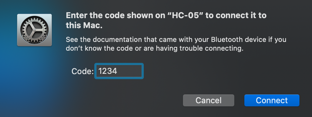
- Click ‘connect’, then ‘Options’ to enter the passcode, which is 1234 by default. (If 1234 doesn’t work, try 0000)

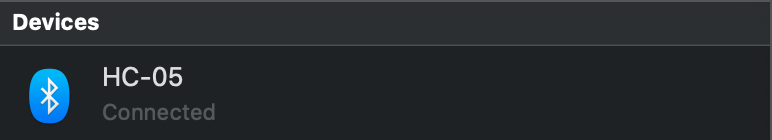
Now you should be connected to the chip, the red LED on your HC-05 should be blinking. (If not, see Troubleshooting/HC-05 Not Blinking)
Now we’ll locate where the bluetooth port is (you’ll need it later)
- Open up Terminal.
- Type in the command
ls /dev/tty* | grep HCand press enter to locate your bluetooth port. Note it down for future reference.
If this outputs nothing, check that your HC-05 is powered on and blinking.
Now you’re good to go!
Connecting HC-05 to Windows
- Navigate to Bluetooth Settings on your PC, go to ‘Add Device’ and add the HC-05 Module
- If it asks for a password use ‘1234’ as this is the default password for the module
- After it is connected, open up Device Manager on your PC. You can type in ‘Device Manager’ on the Windows Taskbar Search to find it.
- Once here, click on Ports and you should see the HC-05 listed as ‘Standard Serial over Bluetooth Link (COMx)’
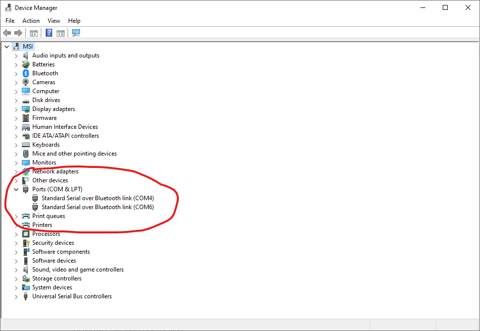
There may be two ports listed, but only one will work with Processing. We will test later which one, but make note of both of the COM numbers listed. Additionally, if you have anything else connected to your computer, such as your Arduino, you may see it under Ports, this is okay!