8: Communication Protocols
Lecture Slides
About this Project
In this project, you will get to design your very own video game console. Using a joystick, OLED display, and a whole lot of code you will get to create your very own GameBuino and video game to play with it! This project is fairly complex, we highly encourage you to start early and ask questions when you need help.
Prerequisites
Parts List
| Part | Quantity | Estimated Cost | Example Vendor |
|---|---|---|---|
| OLED Display | 1 | $14.99 (pack of 5) | Amazon |
| Joystick | 1 | $13.29 (pack of 10) | Amazon |
| Breadboard | 1 | $12.08 (pack of 6) | Amazon |
| Jumper Wires | 10 | $6.98 (pack of 120) | Amazon |
| Arduino Nano | 1 | $19.99 (pack of 3) | Amazon |
- Optional: pushbuttons, buzzers, leds
Total estimated cost: $13.59 per team of 2
Part 1: Designing your Gamebuino
The first part of the GameBuino project is to set up the hardware portion, both wiring and testing it. For the checkoff, you only need to have the Joystick and OLED Display, but we encourage you to think about what parts you might want to add to your console for the competition, like a buzzer for game music, an LED for special effects, or buttons for additional controls! Be creative, we can’t wait to see what you come up with.
Section 1: Wiring
To start with the hardware, we first need to wire both the OLED display and joystick.
The OLED display uses i2c communication protocol, meaning that it uses two pins for communication, Serial Data (SDA) and Serial Clock (SCL). On Arduino Nano, the pin A4 is used for SDA, and pin A5 is used for SCL.
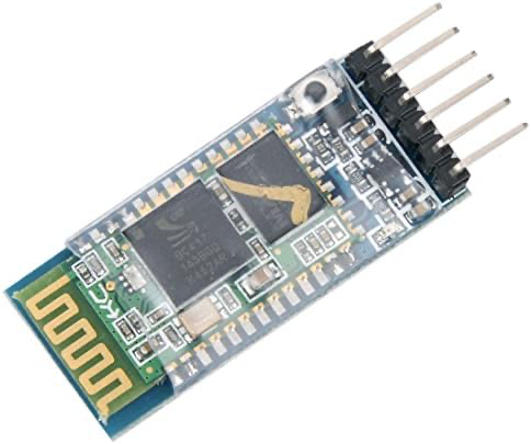
The joystick has three pins for measuring input: VRX, VRY, and SW. VRX tracks the joystick position on the X axis, VRY tracks the joystick position on the Y axis, and SW tracks the built in joystick button. You can use male-to-female jumper wires to wire the Joystick and then tape it down securely, if you can’t find male-to-female you can always use female-female and male-male together.
Optionally: You can also wire any other components you would like to use in your game console, like buttons, LED’s, or a piezo buzzer.
| Wiring | |||
| OLED Display | Joystick | ||
| GND | Ground | GND | Ground |
| VCC | 5v | +5V | 5v |
| SDA | A4 | VRX | Any Analog Pin |
| SCL | A5 | VRY | Any Analog Pin |
| SW | Any Digital Pin | ||
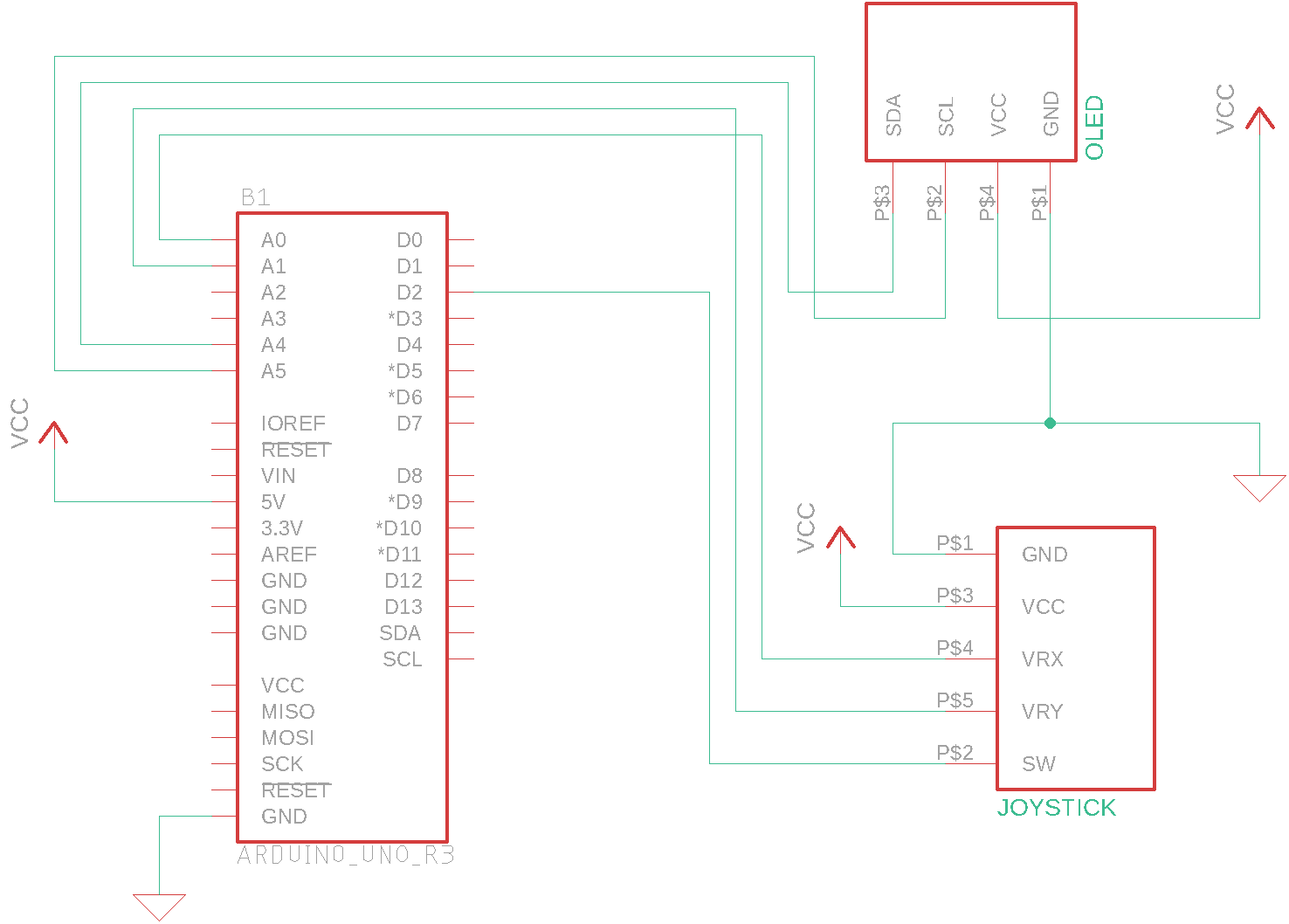
Schematic
TIPS:
- If you have having trouble with this, try wiring and testing each part separately instead of doing both at the same time
- Make sure you have no open circuits.
Section 2: Your Joystick
Next, we need to calibrate the joystick and ensure that it works for our game. This will require writing some software to check what values your joystick changes on. The idea behind this is to write code to output the values of the X axis, Y axis, and Switch so that you can see how they change when you move the joystick.
Here is some pseudo code to get you started:
Declare your pins for VRX, VRY, and SW

SETUP:
    Start the Serial Monitor
    Initialize Pin Modes

LOOP:
    Read the analog values of VRX and VRY
    Read the digital value of SW
    Serial.print("X: ");
    Serial.print(vrxValue);
    Serial.print("\t"); //this prints a tab
    Serial.print("Y: ");
    Serial.print(vryValue);
    Serial.print("\t"); //this prints a tab
    Serial.print("SW: ");
    Serial.println(swValue);
Note: to initialize the SW pin mode, you’ll want to use INPUT_PULLUP for the mode, as that is what the joystick is designed for.
Next you’ll want to run this code and write down values you’ll want to use for comparison. Find out what value the joystick outputs when you hold it up, left, right, and down, and write them down. You might also want to write down what values are outputted when the joystick is in it’s “DeadZone”, which is when you’re not moving it all. Finally, write down what value you get for the Switch when you press down on the joystick, you will be using this as the button in your game.
Now that you have those values, write some more code to simulate how the game will react to joystick input. The code should write “UP” to serial monitor when you are hold the joystick up, “DOWN” when you hold it down, “LEFT” when you hold it left, “RIGHT” when you hold it right, and “BUTTON PRESSED” when you press the button.
Here is some pseudocode to get you started:
Declare your pins for VRX, VRY, and SW

SETUP:
    Start the Serial Monitor
    Initialize Pin Modes

LOOP:
    Read the analog values of VRX and VRY
    Read the digital value of SW
    IF joystick is up:
        print "UP"
    IF joystick is down:
        print "DOWN"
    IF joystick is left:
        print "LEFT"
    IF joystick is right:
        print "RIGHT"
    IF joystick button is pressed:
        print "BUTTON PRESSED"
*Note: How do you tell if joystick is being held in a certain direction? Compare the threshold values you found with the previous code, for example, if VRY is 1023 when you hold it up, and 550 at the center, maybe check if VRY>900 for the comparison.
Section 3: OLED
Now that we have our Joystick working, let’s make sure that our OLED Display works! This is a beautiful display that we can control really closely, you can set each individual pixel! To make sure that it works, we’re going to need to download Arduino libraries and then run a code example designed for our OLED.
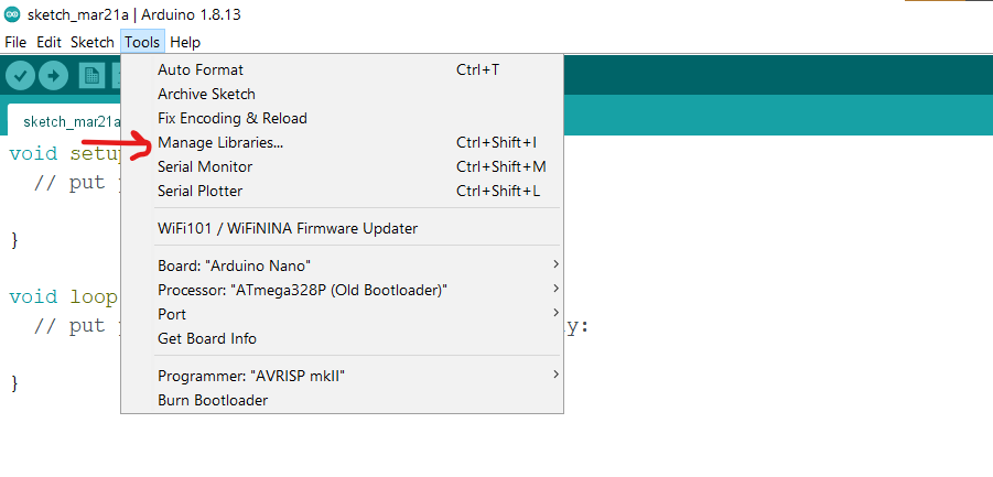
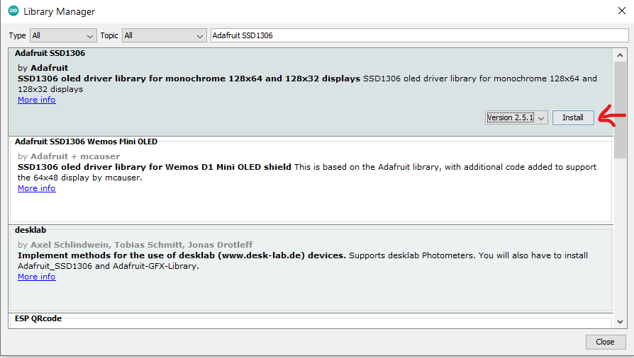
- Install the Arduino libraries “Adafruit GFX Library” and “Adafruit SSD1306 Library”. To do this first, open the Arduino IDE and make a new sketch. Then click on the bar at the top that says Tools, then click Manage Libraries. Tools>Manage Libraries. A popup should come up that says Library Manager.
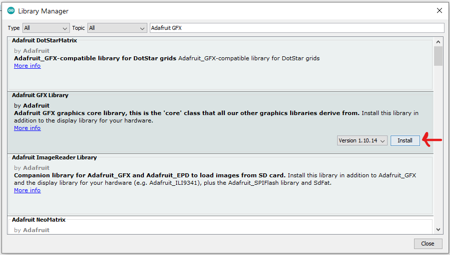
- Next, search for Adafruit GFX and click install.
- Next, search for Adafruit SSD1306 and click install.
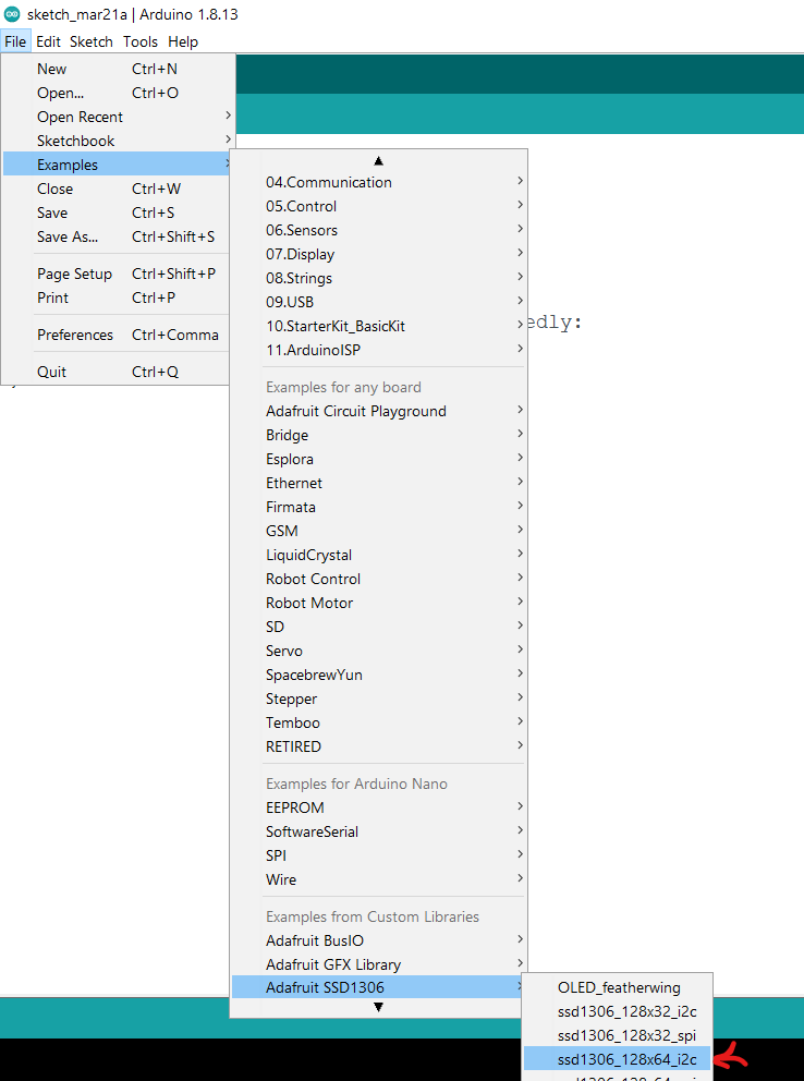
- Next, go to Files>Examples>AdafruitSSD1306>ssd1306_128x64_i2c. This should open up the example code sketch.
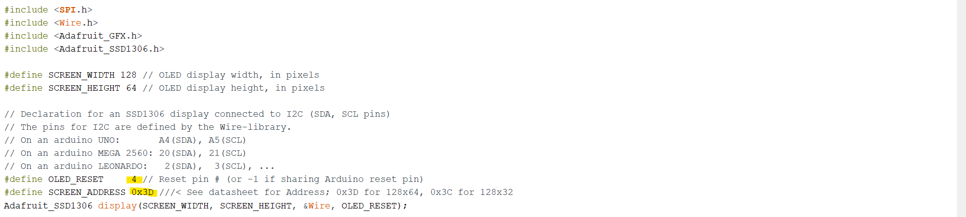
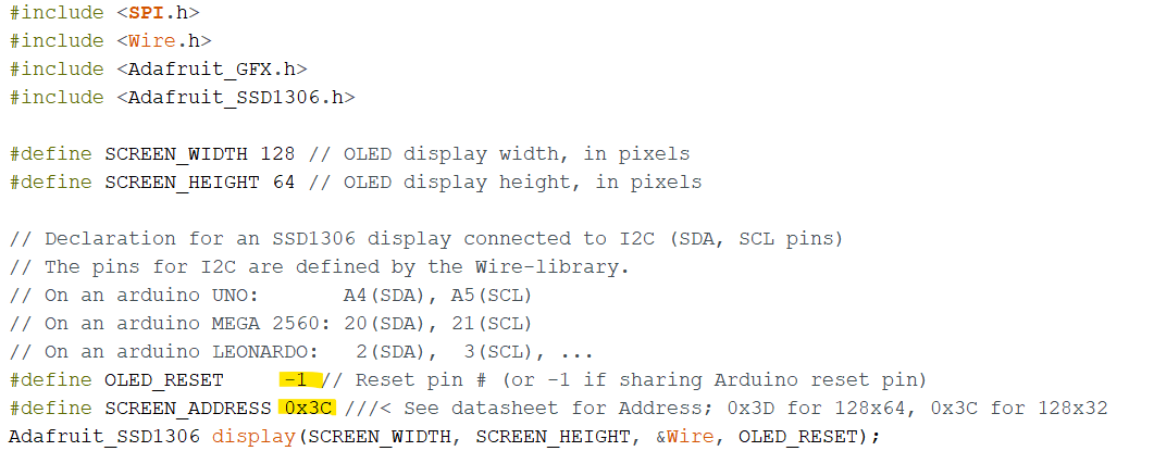
- Next, edit the sketch to change OLED_RESET to -1 and SCREEN_ADDRESS to 0x3C. It says that Ox3C is only used for 128x32, however our OLED’s are made by a different manufacturer that uses Ox3C for 128x64.
 →
→
-
Next, save the edited file, it will require you to name it something since you can’t edit the actual example file.
-
Finally, upload the software to your Arduino Nano and you should see animation happening on the screen! If you don’t see anything, double check that you wired it correctly.

- Congratulations, you’re done with the hardware portion of your GameBuino, now onto coding the actual game!
Part 2: Software
Now that we have our hardware ready, let’s program our very own game! For the purposes of checkoffs, you will be programming a simple game of TicTacToe. If you missed the lecture, make sure you read the slides to learn about arrays and functions which you will need for this project.
Section 1: Graphics
Since the adafruit graphics library can be complicated and tedious, we have provided you with a TicTacToe graphics display library for you to use which will do most of the hard work for you. (for those who want to try coding graphics themselves, don’t worry, more information on that will be provided in the competition section). Follow these steps below to download and use the TicTacToe graphics library.
- Read over the libraries github README for usage information. Github is a very popular tool for software version control and collaboration, so you might want to spend some time getting used to the website. Here is the link to the TicTacToe graphics library github: https://github.com/PrestonRooker/TicTacToeArduinoOLEDLibrary
- Download the library as a zipped folder via the green button that says code, then hit “Download ZIP”. Or you can use this link: https://github.com/PrestonRooker/TicTacToeArduinoOLEDLibrary/archive/refs/heads/main.zip
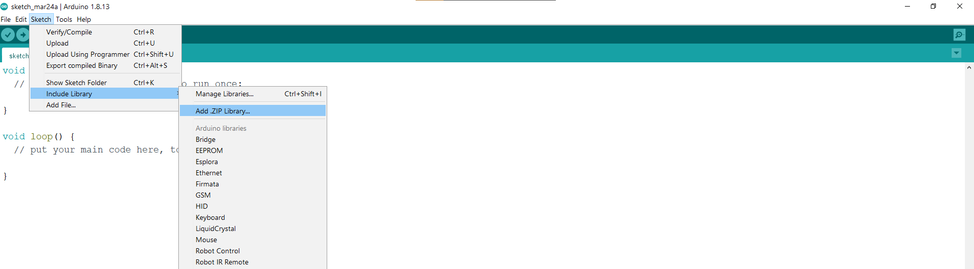
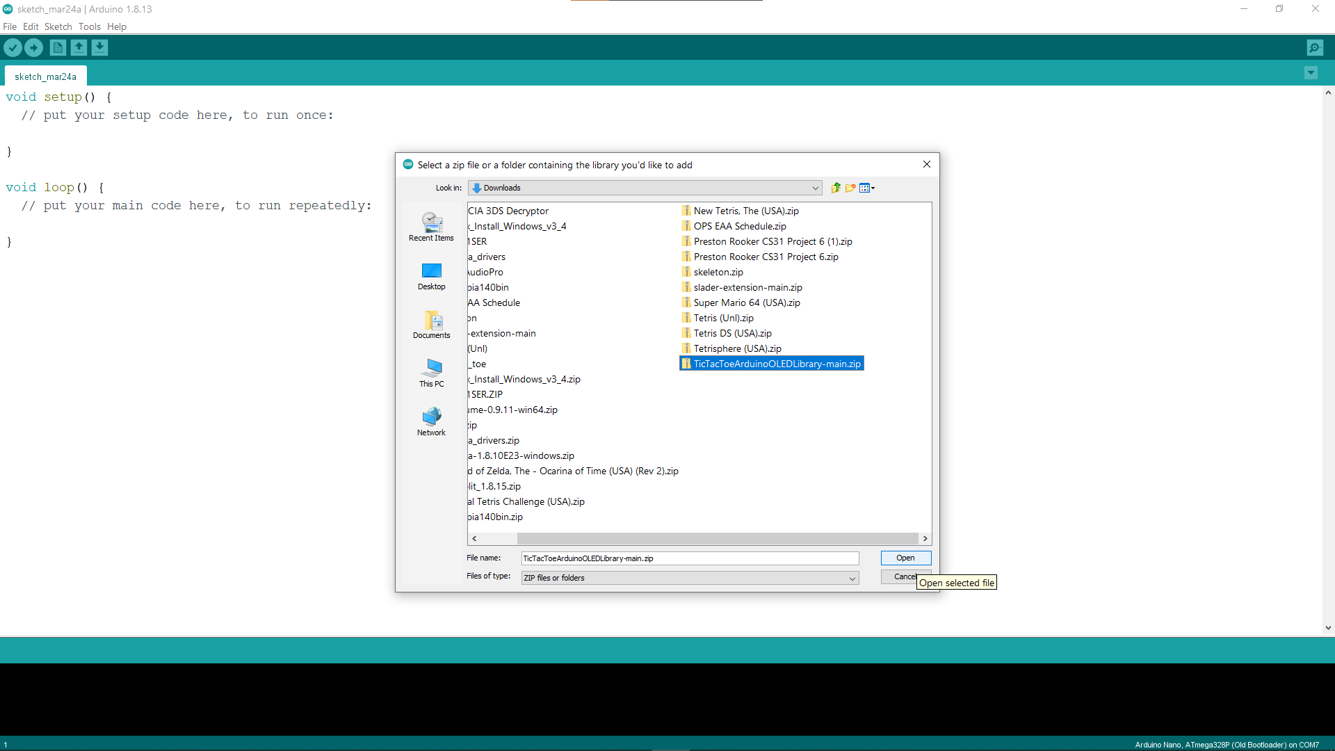
- Next open up a new sketch in the Arduino IDE. Then go to Sketch>Include Library>Add .ZIP Library. Then select the downloaded zipped folder you just downloaded, TicTacToeArduinoOLEDLibrary-main.zip.
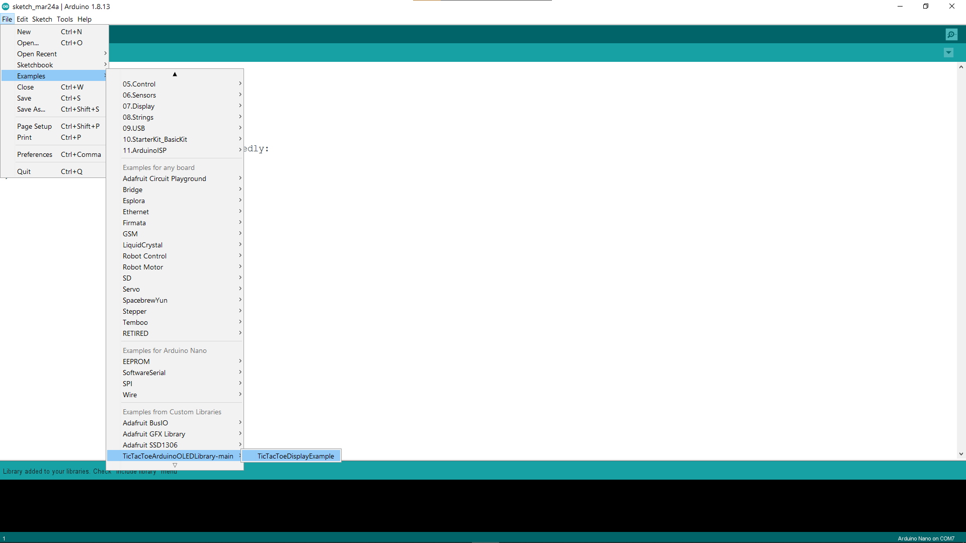
- Now that you have installed the custom library, you can find the example of how to use it under File>Examples>TicTacToeArduinoOLEDLibrary-main>TicTacToeDisplayExample
- From here, read through the example code, and run it on your arduino. Then make a copy of it and try changing things around, and get a general feel for how to use the library.
- Finally, start a new sketch for your GameBuino project, and use the graphics library to give graphics to your TicTacToe game! We suggest making it play through a mock game of Tic Tac Toe with just the graphics and code to make sure you understand how you will use it in the final game. If you have any questions or problems with the library don’t be afraid to ask, our discords are always open :)
Section two: controla’ controla’
Now that you’ve coded the graphics for your TicTacToe game, now’s the time to implement the controls. To control your TicTacToe game, you need to code a way for players to take turns, move between square choices, and select the square where they want to place their piece.
Recall how in the hardware portion you wrote code which detected the direction of the joystick and whether it was being pressed. Reuse that code in your controls code so that the player controls the game using the joystick.
For having the player move between squares, you might find it easier to have them only be able to move left or right and then go to the next row down when they reach the end of the current row. Have players use the joystick button to place their piece on the board.
Once you’re done with this, you should have a game where players take turns dropping X’s and O’s onto the TicTacToe board forever.
Section three - victory?
Now that we have the controls of the game done, the final thing to do is to have a way to detect whether or not a player has won. This will be the complicated part of your code, and I definitely suggest making a separate function for it.
Once you’ve made your function which can detect whether or not a player has won, make sure to call it whenever a player finishes their turn by placing a piece, and end the game accordingly if someone has won.
Make sure your function works for all victory conditions in TicTacToe, including vertical victories, horizontal victories, diagonal victories, and ties.
Tips:
- It might be easier to use a 1D array to represent your TicTacToe board
- If you are having trouble with coding and need more help, definitely reach out to us on discord
Check-offs:
For the checkoff, you should have a functioning game of TicTacToe that can be played with the joystick and displayed on the OLED display. To get checked off you will have to submit a FULL GAME of TicTacToe in your submission form. Click here to submit your project.