Intro to Arduino: Potentiometer Blink
About this Project
In this project, you will be working with microcontrollers which is just a fancy word for a small programmable computer that can coordinate different input/output functions in your circuit. The different components that will be attached to the microcontroller include a potentiometer(input) used as a voltage divider and an LED(output) that will change blinking frequency as you turn the potentiometer knob. This project will fuse both your knowledge on circuits and coding to make a really cool project!
Lecture Slides
Prerequisites
Skills Learned
- Voltage Divider Circuit
- Potentiometer
- Choosing Arduino Pins
- Arduino Programming
Parts List
| Part | Quantity | Estimated Cost | Example Vendor |
|---|---|---|---|
| Breadboard | 1 | $1.50 | Amazon |
| Potentiometer | 1 | $0.95 | Adafruit |
| LED | 1 | $0.25 | Digikey |
| 130 Ohm Resistor | 1 | $0.03 | Digikey |
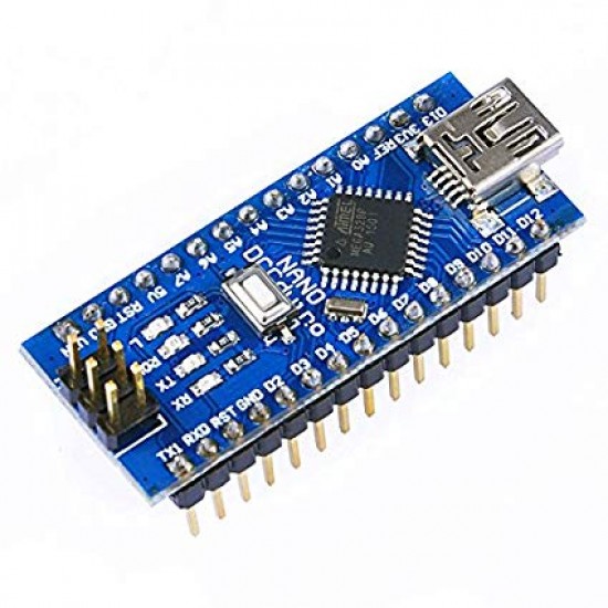
| Arduino Nano | 1 | $4.00 | Amazon |
| Mini USB Cable | 1 | $2.00 | Mouser |
Total estimated cost: $8.73 per member
If reusing Breadboard/Arduino/MiniUSB: $1.23 per member
Background
Voltage Dividers
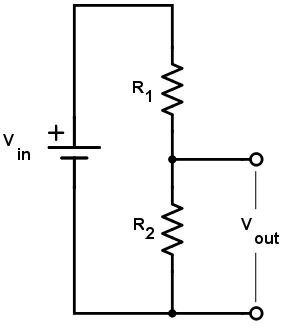
- A voltage divider is a circuit that consists of 2 resistors R1 and R2, and an input voltage Vin.
- Vout is a measurement across the resistor closest to GND (R2) and its value depends on the ratio of R1 and R2.
- Using Ohm’s Law (V=IR), we can determine the exact value of Vout
- Equivalent Resistance Req = R1 + R2 (add when resistors are in series)
- Vin = I * Req
- We can rearrange the equation to get: I = Vin/Req = Vin/(R1 + R2)
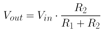
- Vout = V2 = I * R2
- We can plug in I found previously into this equation since current through R1 has the same value as R2 to get: Vout = Vin * (R2/(R1+R2))
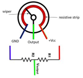
Potentiometers
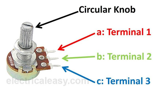
- All potentiometers have a total resistance associated with it and in this project, we have a 10K Ohm one. A potentiometer splits this 10K resistance into 2 resistances R1 and R2, whose values depend on how much the knob of a potentiometer is turned. See figure 2.
- You can think of a potentiometer as a variable voltage divider because there are two resistances involved. By turning the potentiometer knob (wiper), the ratio of the 2 resistances in the potentiometer will change and thus Vout will also change.
- There are 3 terminals, and the outermost terminals (1 and 3 in the figure below) are connected to either GND or VCC. The middle terminal(T2) should be connected to an INPUT pin on the Arduino since we want to READ the voltage of the potentiometer at that pin with respect to GND. The voltage you would be reading if looking at Figure 2 is the Vout or the voltage across R2. This setup will create a voltage divider circuit, where you will be able to change R1 and R2 by turning the knob.
- NEVER CONNECT THE MIDDLE TERMINAL TO GND OR VCC
- If you turn the knob all the way to the left so that R2 is 0 Ohms (no resistance) in the example below and then connect the output terminal to VCC, there will be a short from VCC to GND and your Arduino will fry/smoke/break which is NOT GOOD!
- The same thing will happen if you turn the knob all the way to the right so that R1 has no resistance and connect the middle terminal to GND so that there is also a short from VCC to GND.
- Always check this before doing anything else.
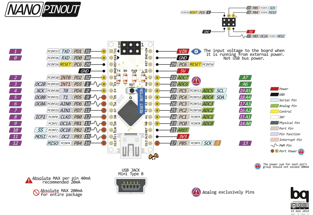
The Arduino Nano’s Pins
- There are 3 types of programmable pins on the Arduino, but we will only focus on the first two types for this project. The pins can either read a voltage value or output a voltage.
- Digital INPUT/OUTPUT pins
- These are labelled with the letter “D” on the Arduino Nano.
- The digital pins will use a HIGH or LOW voltage to read/output. HIGH for the Arduino Nano equates to 5V and LOW is 0V. For the project, we want to have our LED turn completely ON/OFF instead of gradually dimming/becoming brighter, so we connect the LED to a digital OUTPUT pin.
- Input: The pin will read either a HIGH(1) or LOW(0) voltage
- Output: The pin will output either a HIGH(1) or LOW(0) voltage
- Analog INPUT pins
- These pins are labelled with the prefix letter “A” on the Arduino Nano.
- Analog input pins will map a voltage between 0V and 5V to a digital number from 0-1023.
- Note(not necessary to know): There are 1024 total digital values that can be represented because the Arduino uses a 10 bit ADC(analog to digital converter), meaning there are 2^10 = 1024 values that 10 bits can represent.
- In this project, we want to connect the middle pin of the potentiometer to an analog input pin since we want to change the LED’s blinking frequency AS we are turning the potentiometer knob and can do so using a range of input values.
- Digital PWM OUTPUT pins
- To output an analog-like signal, PWM(pulse width modulation) pins are used. More on this in later projects. This is not used in this project.
- Digital INPUT/OUTPUT pins
The Arduino IDE
- The Arduino Integrated Development Environment (IDE) uses syntax that is very similar to C++
- The concepts that will be applicable when coding in the Arduino IDE are:
- declaring and initializing variables
- loops
- arrays
- strings
- functions
- libraries and #include statements
- #define statements
- This environment allows one to provide logic and functionality to their circuit connected to the Arduino Nano. After writing a program in the IDE, the program can then be compiled and uploaded to the Arduino board from the IDE itself.
The Arduino IDE Coding Structure
- The coding structure for a typical Arduino program:
- #define
<pin#> - This allows one to refer to the variableName instead of the pin# so that it is easier to read and if the pin# changes, you would only need to change the pin# in the define statement rather than in the entire program.
- setup()
- Runs once
- Define your pins to be an INPUT or OUTPUT pin
- Set the serial baud rate and allow you to use Serial.print()
- loop()
- Runs forever, like a forever for loop
- Read inputs from pins or output to a pin
- #define
Typical Arduino Functions
- digitalWrite(pin #, HIGH/LOW)
- outputs discrete voltage (HIGH/LOW)
- analogRead(pin #)
- reads variable voltage (outputs a range from 0-1023)
- delay(milliseconds)
- pauses for a specified time
- Serial.print(text)
- prints out text to the serial window
- Serial.println(text)
- same as above, but adds a new line afterward
- Note: Make sure you call Serial.begin(9600) in setup() or this won’t work!
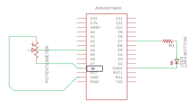
Project Specification Part 1 (Building the Schematic on your Breadboard)
There are two parts to the schematic below. On the left side, you can see the potentiometer symbol with the two OUTER terminals connected to GND and 5V(could also use Vin) and the middle terminal connected to an analog input pin (A4). MAKE SURE THE MIDDLE TERMINAL IS NOT CONNECTED TO EITHER 5
On the right side, you can see the LED circuit consisting of an LED and resistor in series (to limit the current going through the LED). The resistor R1 is connected to the digital pin D7 which you will program in the Arduino IDE to output 5V(turn on the LED) or 0V(turn off the LED).
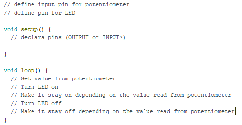
Project Specification Part 2 (Writing the Arduino Program)
- Using the coding structure mentioned before and the pseudocode below, program the LED to turn on/off for a certain amount of time based on the value from the potentiometer. Some useful functions include:
- pinMode(
, <INPUT/OUTPUT>); - Serial.begin(9600);
- Serial.print(“Some statement to print to the serial monitor on your laptop”);
- digitalWrite(
, <HIGH/LOW>); - analogRead(
) - delay(<# of milliseconds>)
- Note: there are 1000 milliseconds in 1 second
- pinMode(
Checkoff Questions
Here are some questions you can use to test understanding of the concepts involved in this project:
- What is the difference between a digital and an analog signal?
- Digital: either LOW or HIGH (OFF or ON, square wave);
- Analog: Has a lot of possible values (0-255) making any transition smooth and continuous; emulated by PWM (they must answer this last part too)
- When do the setup and loop functions run, and what do they do?
- Setup function runs once when the Arduino turns on, then the loop function runs repeatedly every clock cycle, indefinitely
- How does a voltage divider work?
- When two resistors are in series with each other and connected to a voltage source, the voltage across each resistor is split in proportion to their resistance values.